Welcome —finally— to my guide on how to control RGB LED lights from your smartphone or web browser by making use of the DMX protocol.
Some background
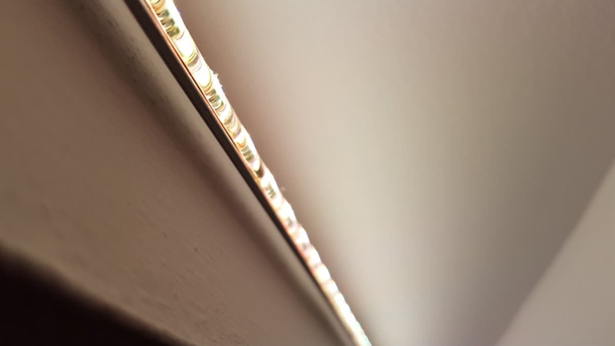
First of all, a bit of background history on how this all came to be. I started this project way back in February 2015 when we first installed RGB LED strips in my room. In order to power them, we got a regular 12V power supply, along with a DMX decoder to control the full 
-

- Lights On
-
- Lights Off
As it turns out, the DMX decoder included a wireless remote that’s supposed to help you change the color in display with an iPod-like wheel, along with the brightness and more. However, this remote just plain sucks; the “color wheel” is awful at best, and there’s no easy way to come back to the color combinations you’ve found to be the most comfortable.
-
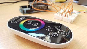
- The dreadful remote

There are countless other ways to solve this problem, but the aim of this DIY project was to figure out a new and better way to control the LED lights, while keeping the already present DMX decoder. To achieve our goal, I settled on just building a mobile-ready web interface and connect it to an Arduino board.
The bill of materials
Let’s talk details. Here’s a list of the most important components you will want to use to build this kind of system:
- The RGB LED lights (duh..).
- A DMX decoder. I used a 3-channel one like this.
- An Arduino Mega 2560 (rev. 3). I started this project with one of my Arduino UNOs, but after getting stuck at some point, I realized the board was lacking RAM… who would have guessed 2kB wasn’t enough memory? I even tried using the “hidden” F syntax, but that didn’t help much either; in the end, I solved the issue upgrading to an Arduino Mega 2560, based on the same architecture as the UNO but offering up to 6kB more RAM!
- The Arduino Ethernet Shield. You can find them online.
- Cat-5 Ethernet cable and a microSD card for the Ethernet board.
- A MAX485 transceiver. Here’s the data sheet.
- A 100Ω resistor.
- A reliable 12V power supply of your choice for the LED strips.
- A 9V / 500mA power adapter for the Arduino board. This guide will help you find an appropiate one.
- A breadboard, a few jumper wires, and the necessary length 3-wire electric cable to connect the Arduino to the DMX decoder.
How it works
So, once everything is setup, let’s take a look at how the system works.
You start by accessing the IP address of the Arduino (Ethernet Shield) from your browser of choice, at which moment you’re presented with a webpage that looks something like this:
-
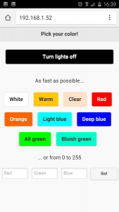
- Mobile webpage screenshot

As you can see, it’s nothing fancy, but it’s as functional as it gets. On the upper side it presents a list of buttons for the LED colors I have found to be the most pleasant, as well as three text fields right below to input any RGB value you want.
Anyway, once you select any of the colors, the software will encode the RGB color combination as an HTTP GET request, effectively sending the r, g, and b values back to the Arduino, as you can see at this point by checking the URL address. It will look something like this:
http://192.168.1.52?r=255&g=255&b=255
After receiving the aforementioned request, the Arduino will generate a DMX signal corresponding to the user input and making use of the rest of electronics will then send it to the DMX decoder, whose job will now be limited to powering up the LED strips to the expected color.
Easy, huh?
Putting it all together
That’s cool and all… but how the heck do I build this thing?
Hardware setup overview
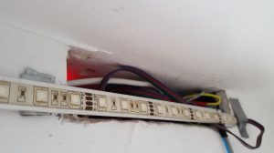
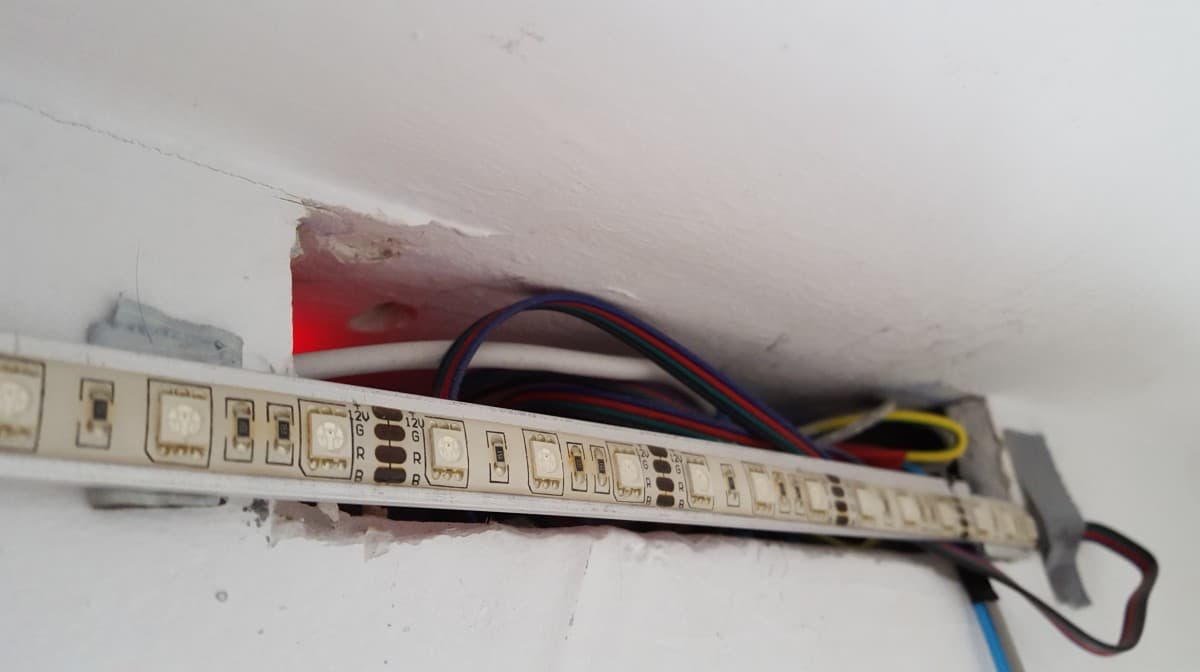
Let’s start with the power side of things. Typically in a higher-power LED installation, you’d connect the lights to the 12V power supply of your choice and be done with it. However, in this case, we’ll place the DMX decoder in between, so now the power supply powers up the DMX box and then the LED strips plug into its output.
My specific DMX decoder has 3 pins for DMX input, corresponding to GND reference voltage and D+ and D- signals. Here’s where that 3-wire cable hooks up, connecting the box to the Arduino and electronics.
On the other side of the setup resides the Arduino Mega microcontroller attached to the Ethernet Shield. The board is also connected to a breadboard, which houses all the electronic components, along with 9V power and a Cat-5 Ethernet cable.
-
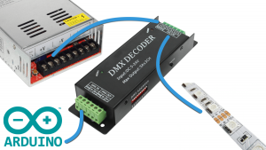
- Hardware setup overview

Electronics
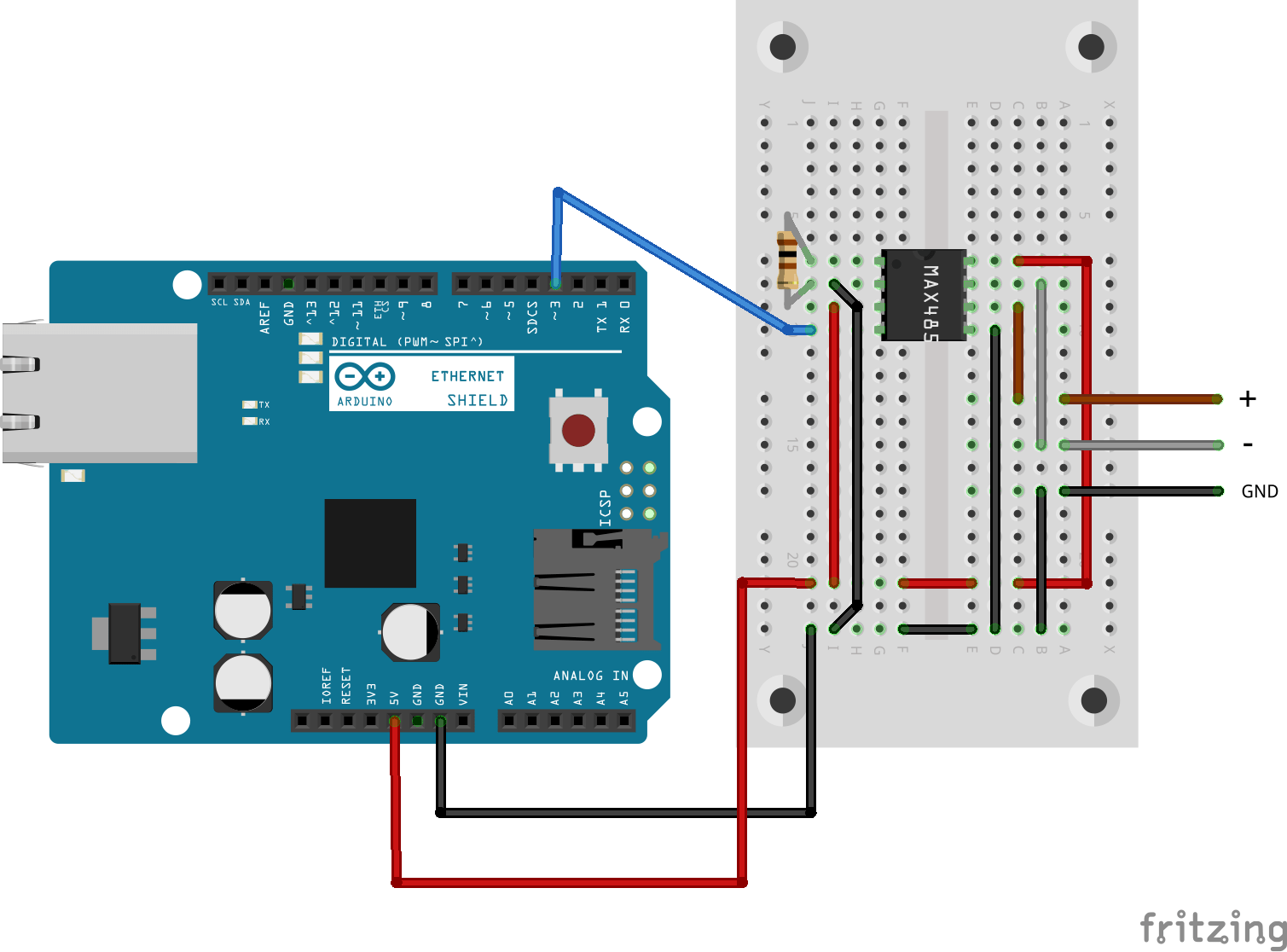
The whole circuitry is shown in the following Fritzing diagram. As explained here, here, and there, this combination of a MAX485 transceiver, a 100Ω resistor, and a couple jumper wires will handle the conversion from the digital output of the Arduino to an electrically-compliant RS-485 DMX512 signal.
-
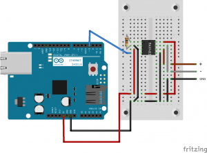
- Electronics diagram
Software setup overview
Finally, now that we’re done with the hardware side of things we can switch our focus to the software that’s running on the microcontroller. If you prefer git-cloning to copy-pasting, you can easily do so as the source code is now available as a repository on GitHub.
The center piece is the library DmxMaster (formerly DmxSimple) by TinkerKit. Once installed via the downloaded *.zip file, it will be responsible for generating the digital output off PIN #3 that plugs into the transceiver to generate the aforementioned DMX signal.
Here’s how it’s called:
DmxMaster.write(1, 255); // channel (1: r, 2: g, 3: b), value (0 - 255)
The webpage: index.htm
Then we have the webpage itself. Stored in the microSD card, it’s just an HTML file I wrote by making use of jQuery Mobile because I’m lazy and I don’t like writing CSS.
Notice the file name is index.htm and not index.html. This is by no means an accident, as it turns out the Arduino SD card library has trouble reading files with extensions longer than 3 characters as it uses the legacy 8.3 filename convention.
As we’ve seen before, it consists of 9 direct-access-to-color buttons, a form with 3 text fields for custom RGB input, and an extra large button for turning the lights off. Here’s the full code:
<!DOCTYPE html>
<html>
<head>
<!-- Main -->
<title>Arduino says: Pick your color!</title>
<meta name="viewport" content="user-scalable=no, width=device-width, initial-scale=1">
<meta charset="utf-8">
<!-- jQuery Mobile -->
<link rel="stylesheet" href="http://code.jquery.com/mobile/1.4.5/jquery.mobile-1.4.5.min.css">
<script src="http://code.jquery.com/jquery-1.11.1.min.js"></script>
<script src="http://code.jquery.com/mobile/1.4.5/jquery.mobile-1.4.5.min.js"></script>
<!-- Custom CSS -->
<style type="text/css">
.centered {
text-align: center;
}
</style>
</head>
<body>
<div data-role="page">
<div data-role="header">
<h1>Pick your color!</h1>
</div>
<div data-role="content">
<a href="/?r=0&g=0&b=0" class="ui-btn ui-corner-all" style="background: black; color: white;">Turn lights off</a>
</div>
<p class="centered">As fast as possible...</p>
<div class="ui-grid-d centered">
<!-- Buttons for your favorite colors here -->
<a href="/?r=255&g=255&b=255" class="ui-btn ui-corner-all ui-btn-inline" style="background: white; text-shadow: none;">White</a>
<a href="/?r=255&g=90&b=0" class="ui-btn ui-corner-all ui-btn-inline" style="background: #FFC800; text-shadow: none;">Warm</a>
<a href="/?r=255&g=128&b=50" class="ui-btn ui-corner-all ui-btn-inline" style="background: #FFE1C8; text-shadow: none;">Clear</a>
<a href="/?r=255&g=0&b=0" class="ui-btn ui-corner-all ui-btn-inline" style="background: red; color: white; text-shadow: none;">Red</a>
<a href="/?r=255&g=60&b=0" class="ui-btn ui-corner-all ui-btn-inline" style="background: #FF6400; color: white; text-shadow: none;">Orange</a>
<a href="/?r=0&g=255&b=255" class="ui-btn ui-corner-all ui-btn-inline" style="background: #00FFFF; text-shadow: none;">Light blue</a>
<a href="/?r=0&g=0&b=255" class="ui-btn ui-corner-all ui-btn-inline" style="background: #0000FF; color: white; text-shadow: none;">Deep blue</a>
<a href="/?r=0&g=255&b=0" class="ui-btn ui-corner-all ui-btn-inline" style="background: #00FF00; text-shadow: none;">All green</a>
<a href="/?r=0&g=255&b=128" class="ui-btn ui-corner-all ui-btn-inline" style="background: #00FFC8; text-shadow: none;">Bluish green</a>
</div>
<p class="centered">... or from 0 to 255</p>
<form method="get">
<fieldset class="ui-grid-c centered">
<div class="ui-block-a">
<input id="red" type="text" name="r" placeholder="Red" data-mini="true">
</div>
<div class="ui-block-b">
<input id="green" type="text" name="g" placeholder="Green" data-mini="true">
</div>
<div class="ui-block-c">
<input id="blue" type="text" name="b" placeholder="Blue" data-mini="true">
</div>
<div class="ui-block-d">
<input type="submit" value="Go!" data-mini="true">
</div>
</fieldset>
</form>
</div>
<footer class="centered"><small>© Pol Mesalles Ripoll, 2016</small></footer>
</div>
</body>
</html>
As a final remark, you can see that jQuery scripts and styles are downloaded from a CDN instead of being read from the SD card. That’s because this approach is simply put waaay faster. And if one day the internet connection cuts out, the webpage will keep working; it just won’t look this fancy.
The Arduino sketch: final.ino and debug.ino
All this code comes together in the Arduino sketches, a.k.a. the “C++” scripts to be compiled on the microcontroller. If you’re new to the Arduino world, this is as simple as writing your code using the open-source IDE, plugging in your board with a USB type-A to type-B cable, selecting the appropiate board model and serial port, and clicking “Upload”.
When programming, you just need to keep in mind what libraries to include (DmxMaster, Ethernet, SD) , and whether your code should run once (inside setup), indefinitely (inside loop), or be available globally (outside of any function). Here’s the full code, with additional commentary:
#include <DmxMaster.h> // DMX communication
#include <SPI.h> // required for Ethernet library
#include <Ethernet.h> // web server
#include <SD.h> // microSD card access

#define N 24 // max buffer size, corresponding to the response "GET /?r=255&g=255&b=255" (23 characters)

// Ethernet controller
byte mac[] = { 0x90, 0xA2, 0xDA, 0x0F, 0xCD, 0xB1 }; // MAC address for the Ethernet Shield (you'll find it on the sticker)
IPAddress ip(192, 168, 1, 52); // a free local IP of your choice - if you want to use DHCP, check debug.ino
EthernetServer server(80); // web server will be running on port 80 for simple HTTP access

// GET variables
char c; // read buffer
String url; // store buffer
File web;

void setup() {
	url.reserve(N);

	Ethernet.begin(mac, ip);
	delay(1000); // wait for everything to be up & running
	server.begin();

	SD.begin(4);
}

void loop() {
	EthernetClient client = server.available(); // look for incoming clients
	if (client) { // a new client has connected
		boolean newLine = true; // it is, indeed, a new line
		while (client.connected()) {
			if (client.available()) {
				c = client.read(); // will read char-by-char to check for the newline ending
				if (url.length() < N) url += c; // will only keep the "GET" responses, ignore the longer "Referer" ones to avoid confusion

				if (c == '\n' && newLine) { // the HTTP request has ended, now send a reply
					// GET
					if (url.indexOf('?') >= 0) { // check if it's the right "GET" response
						// Obtain each individual R-G-B value and send the corresponding DMX signal to default pin #3
						DmxMaster.write(1, url.substring(8, url.indexOf('&', 9)).toInt()); // R
						DmxMaster.write(2, url.substring(url.indexOf('g', 10) + 2, url.indexOf('&', 13)).toInt()); // G
						DmxMaster.write(3, url.substring(url.indexOf('b', 14) + 2, url.indexOf(' ', 17)).toInt()); // B
					}

					// Send HTTP header
					client.println("HTTP/1.1 200 OK");
					client.println("Content-Type: text/html");
					client.println("Connection: close"); // close connection once we're done
					client.println();

					// Send HTML from microSD card
					web = SD.open("index.htm");
					if (web) {
						while (web.available()) {
							client.write(web.read()); // echo the whole webpage
						}
						web.close(); // finished reading the HTML file
					}

					break; // from while
				}

				if (c == '\n') {
					newLine = true; // it's a new line
				} else if (c != '\r') {
					newLine = false; // still reading that line
				}
			}
		}
		delay(1); // wait for the browser to get the data
		url = ""; // reset buffer
		client.stop(); // close the connection
	}
}
The “production” code is available as final.ino, while debug.ino will throw a couple more errors if certain conditions aren’t met.
Voice control via “Ok, Google”
If you have followed the instructions up until now, you should already have a fully functioning system. The final—and optional— step is to get the lights to turn on by using your voice.
For this to work, you’ll need an Android phone with the Google app installed. You’ll also need to download Tasker and the AutoVoice plugin. Everything is explained better in the video, but here’s a summary:
First of all, make sure the “Ok, Google” command is enabled on your phone by opening the Google App > Settings > Voice > “Ok Google” detection and turning on the first two options. Also grant AutoVoice access to allow for the Google Now integration by going to Settings > Accessibility.
If you’ve never used Tasker before, here’s an introduction. And step-by-step:
- Open up Tasker.
- Create a new profile with the bottom-right “+” button.
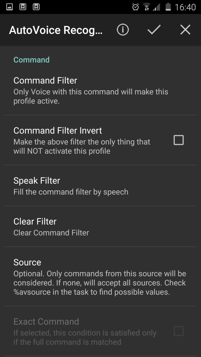
- Choose Event > Plugin > Autovoice > Recognized.
- For the configuration, speak your voice command (i.e., “turn on the lights”) by selecting “Speak filter”.
- After saving the changes, go back to the profiles tab, and a pop-up menu will show up; choose “New Task”.
- Name it as you like and then click the bottom “+” button.
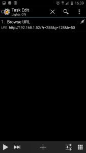
- When asked to select an action, search for “Browser URL”.
- Fill in the URL field with the IP address of your arduino followed by the GET request with any RGB values you like. I chose the equivalent to the “Clear” button from the webpage, like this:
http://192.168.1.52/?r=255&g=128&b=50
You can now repeat the same steps for the “turn off the lights” command and any others you’d like to have. Once you’re done, you should see something like the following in the profiles tab.
-
- Creating a Tasker task

-
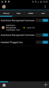
- Tasker profiles view

-
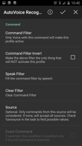
- AutoVoice “Ok Google” setup
And… that’s it. Next time you feel like adding some ambient light, just shout out to your phone “turn on the lights!”… and there will be light.
Conclusions
So… we’re done.
By following this guide you should have been able to build a system that allows for easy control of your RGB LEDs from your web browser or phone via the DMX protocol. If you run into any issues, just let me known in the comments down below and will see what I can do.
-

- Lights Blue

I’ve been using this setup for over a year and it’s been rock solid. So far it has only stopped working because of power outages or because someone (read: not me) has kicked the Arduino board and some of the wires have disconnected.
Regarding power outages there’s not much I can do, but either 3D-printing a case for the system (Arduino + breadboard) or soldering it into a PCB would make it more resistant, plus dust-proof.
When it comes to security, right now there is no data validation, but that shouldn’t be a problem for this kind of system. What’s more worrisome, especially given the status quo of IoT security these days, is whether someone outside your network can gain access to the webpage or the Arduino, and neither should happen as long as your home network and Wi-Fi are safe.
Future work
As I was writing this post, I realized the Arduino Ethernet Shield has since been “retired”. Even though you can still find them online, I’m pretty sure the same can be accomplished using one of the newer Wi-Fi shields. However, compatibility with the MKR1000 and other ARM-based boards is not assured by the DmxMaster library.
Given that this is an open system, adding new features requires nothing but a bit of coding. One of the things I tried to implement was this JavaScript-based web color picker, but in the end I wasn’t happy with the performance and didn’t feel like I would use such an option.
I’ve found that my usage of the “Ok, Google” voice commands has been going down over time, as it feels faster to just ctrl-t into a browser. However, if I could get an Amazon Echo (not available in Spain, or anywhere outside the US for that matter), adding support for Alexa would probably make the system way more useful.
One of the features that could be added in the future are “effects”, like fading and switching between colors, or maybe even sync them to the music or movies playing in the background.
Finally, integrating this webpage-based setup with other home automation systems could turn it into kind of a “hub” for the home, ala Philips Hue but cheaper of course.
Stay tuned for more,